
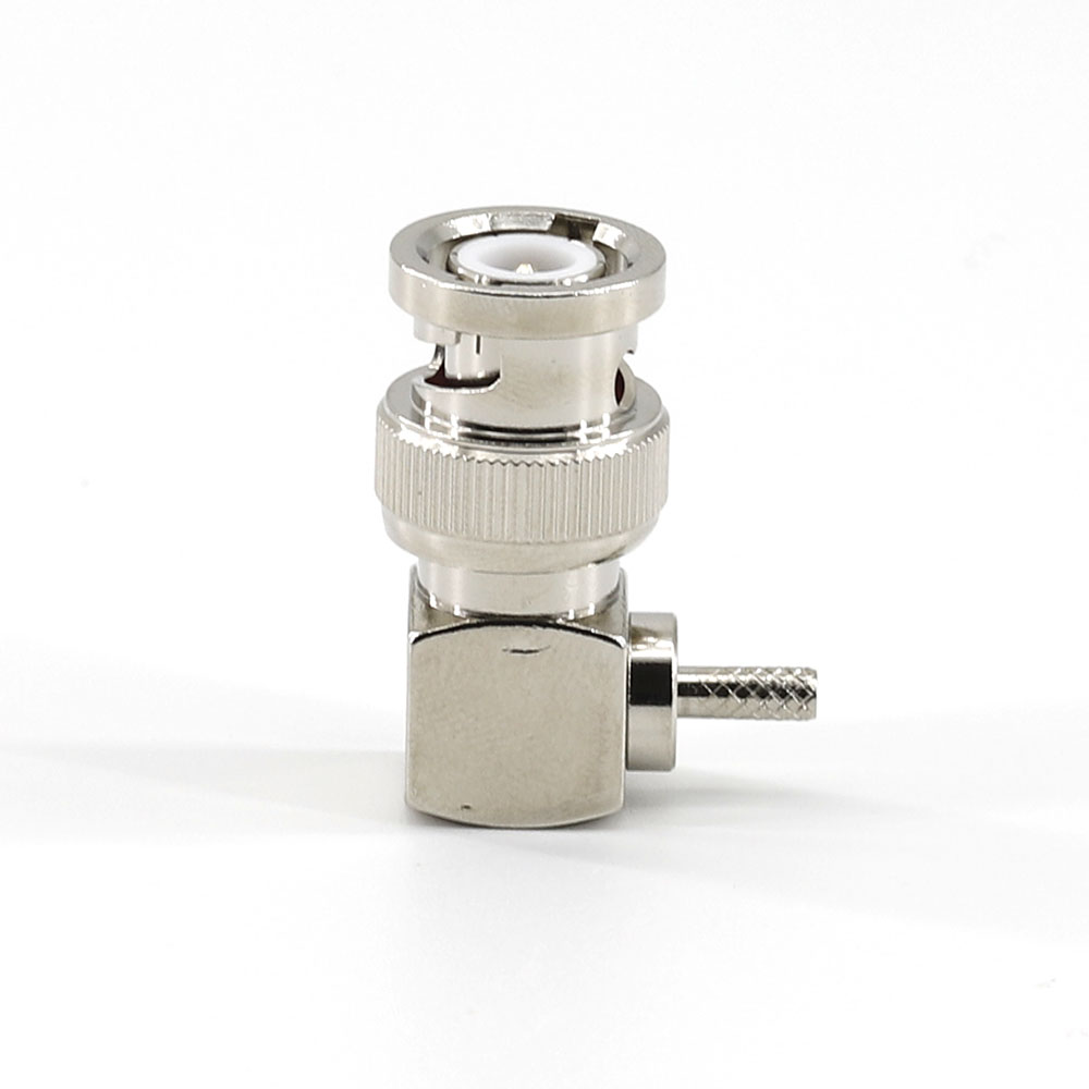
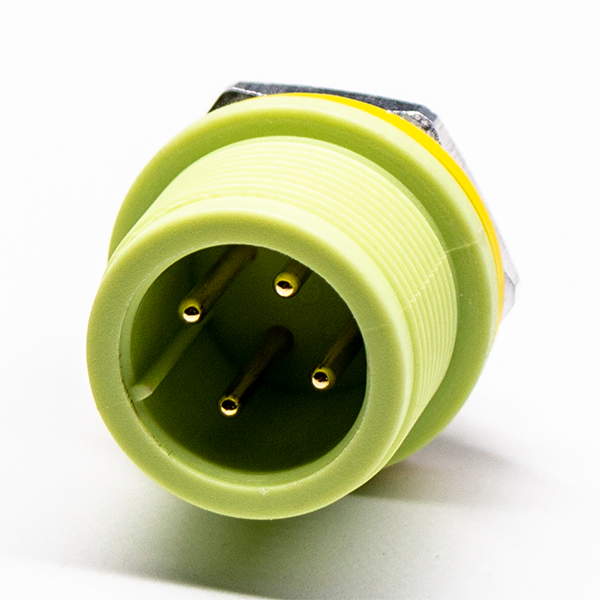
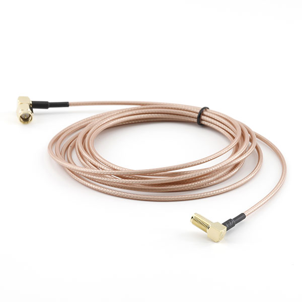
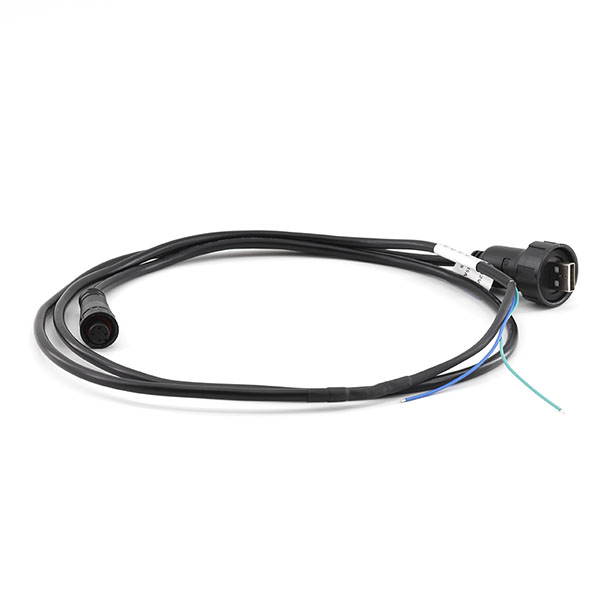
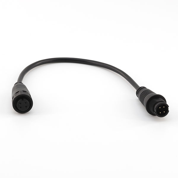







Common I/O connectors include USB connectors, Type-C connectors, HDMI connectors, RJ45 connectors, D-SUB connectors, circular connectors, and industrial I/O connectors, among others.
USB connectors are characterized by their versatility, stable data transmission, and wide range of applications, and are commonly used in computers, smart devices, communication equipment, and industrial terminals.
Type-C connectors support reversible plugging and are characterized by their compact size, fast data transfer speeds, and high compatibility; they are widely used in smart devices and new electronic products.
Industrial I/O connectors are highly reliable and feature vibration resistance, dust resistance, and water resistance, making them suitable for automation equipment, robots, and industrial control systems.
Circular connectors feature a robust design, excellent mechanical strength, and strong environmental adaptability, and are commonly used in industrial equipment, outdoor equipment, and communication systems.
Yes. We can customize the connector type, number of pins, pin pitch, housing design, plating process, protection rating, and mounting method according to customer requirements.
The selection should be based on the device's interface requirements, signal type, current and voltage specifications, installation space, operating environment, and service life.
I/O connectors typically consist of a housing, an insulator, terminals, a shielding structure, fasteners, and other components.
The pin count refers to the number of contact terminals inside the connector; different pin counts can accommodate different numbers of signals and functional requirements.
Common pitch sizes include 0.5 mm, 0.8 mm, 1.0 mm, 1.27 mm, 2.0 mm, and 2.54 mm; the appropriate pitch should be selected based on the equipment design.
Male connectors typically feature a pin structure, while female connectors feature a socket structure; the two fit together to enable signal transmission.
Yes. Depending on the product design and materials used, some I/O connectors can meet high-speed data transmission requirements.
Some products feature a metal shielded housing, which reduces electromagnetic interference (EMI) and improves signal stability.
Common mounting methods include PCB soldering, SMT surface mounting, DIP through-hole mounting, panel mounting, and cable connection.
SMT connectors utilize surface-mount technology, making them suitable for automated production; they take up minimal space on the PCB and offer high production efficiency.
DIP connectors are soldered to PCBs by inserting their pins into the holes, and are characterized by high mechanical strength and a stable connection.
Panel-mount connectors are suitable for devices that require external interfaces, such as industrial control cabinets, communications equipment, and test instruments.
During installation, check the connector orientation, the quality of the solder joints, the mounting structure, and the force applied when inserting or removing the connector to prevent damage to the terminals or poor contact.
Key parameters include rated current, rated voltage, contact resistance, insulation resistance, mating cycle life, operating temperature, and protection rating.
Select based on the application environment; for example, outdoor or industrial environments typically require products with protection ratings such as IP65 or IP67.
Lower contact resistance can reduce signal loss and heat generation, and improve connection stability.
Interference immunity can be improved by adding shielding structures, optimizing terminal designs, and improving grounding methods.